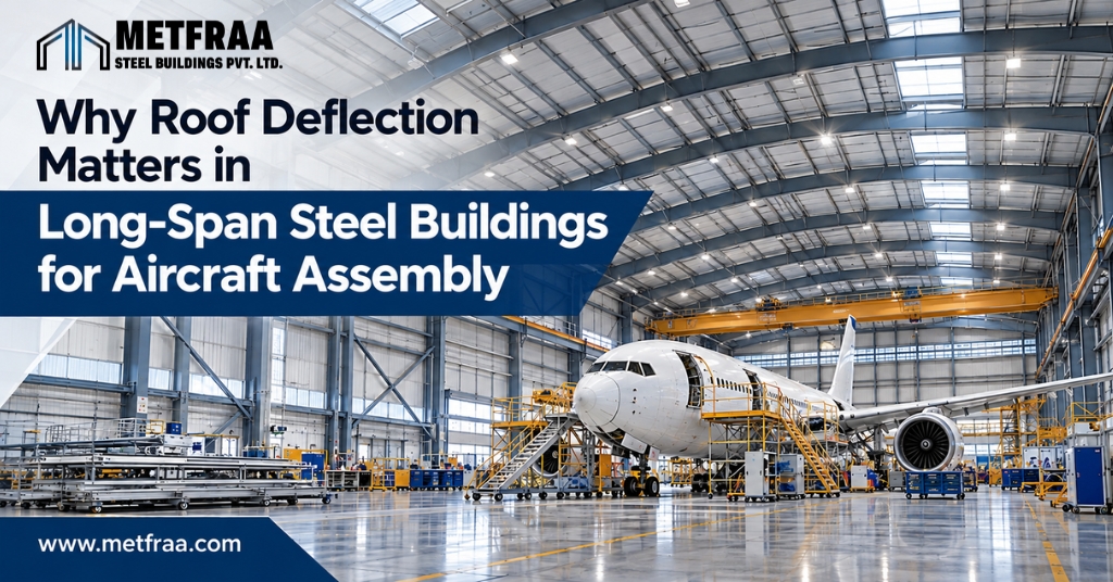
Steel Building design for aircraft assembly requires careful engineering to create large, unobstructed working areas for aircraft positioning, component installation and assembly operations. The structure must provide adequate internal clearance while accommodating the equipment and services needed for day-to-day operations.
Creating a large clear span involves more than selecting stronger structural members. The roof must remain within acceptable deflection limits under relevant loading conditions, with due consideration for roofing components, lifting equipment, lighting, HVAC and other installations. Excessive movement can affect the interfaces between these systems, even when the primary frame has sufficient load-carrying capacity.
The structural arrangement should therefore reflect the actual operating conditions of the facility. Metfraa Steel Buildings approaches long-span industrial projects by considering clear-span requirements, structural performance, equipment integration and future operational needs during the planning process.
Steel Building Design Challenges in Long Spans
As the distance between structural supports increases, roof members must transfer loads across a greater span. This can increase the demand for stiffness and influence the dimensions, configuration and overall behaviour of the framing system.
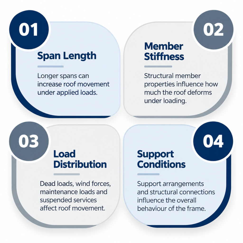
Roof movement depends on several factors, including span length, member properties, support conditions, dead loads, wind forces, maintenance loads and the weight of suspended services. The way structural joints perform and interact with the roof and wall systems also affects the building’s overall behaviour.
For an aircraft assembly facility, the design must satisfy the required working envelope without compromising the performance of connected components. Evaluating the complete structural arrangement helps determine whether the proposed Steel Building can accommodate its intended loads and operating conditions.
Why Roof Deflection Matters in Aircraft Assembly Buildings
Aircraft assembly buildings must provide sufficient space for oversized components, specialised lifting systems and complex overhead equipment. The roof may support ventilation equipment, lighting, cable trays and other services that require adequate clearance and reliable support.
Uncontrolled movement can affect cladding joints, roof drainage, suspended installations and their connections. If these components cannot accommodate the expected displacement, the building may experience maintenance difficulties or reduced service performance.
Where overhead cranes or specialised lifting systems are installed, the relationship between frame movement and equipment operation also requires attention. The design objective is to achieve the necessary clear span while maintaining suitable strength, stiffness and compatibility with the facility’s operating systems.
Start With the Required Clear Span
The required span should be established from the aircraft assembly process rather than from a standard industrial layout. The building layout must account for aircraft size, component movement, equipment access and the working space required for assembly and installation.
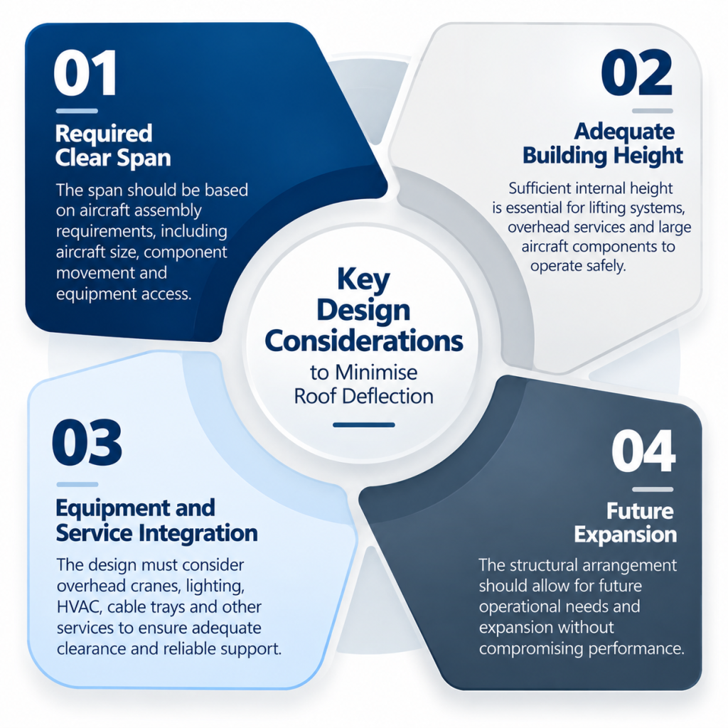
A column arrangement suitable for a conventional warehouse may obstruct aircraft movement or restrict the positioning of assembly equipment. Internal height is equally important because lifting systems, overhead services and large components must operate within the available space.
Before selecting the structural system, the project team should establish:
- Required clear width
- Building height
- Aircraft access and movement requirements
- Crane or lifting requirements
- Equipment locations
- Utility routes
- Future expansion requirements
These inputs provide the basis for determining the framing arrangement and support locations. Identifying these requirements at the initial design stage allows engineers to compare different structural solutions before finalising fabrication and installation plans.
Choosing the Right Structural System for a Steel Building
Large-span facilities can use rigid frames, built-up members, trusses or combinations of structural systems. The appropriate arrangement depends on the span, loading conditions, roof geometry, internal height and operational requirements.
No single framing configuration is suitable for every application. The design must balance load-carrying capacity, stiffness, usable space and construction practicality. Transportation limits, connection details, fabrication methods and erection sequencing can also influence the final selection.
For an industrial Steel Building, structural efficiency should be assessed alongside installation and maintenance requirements. A well-matched system can provide the required working space while remaining practical to manufacture, transport and assemble. The selection of structural members also plays an important role in fabrication and installation, as explained in this guide to Structural Steel Section Selection.
Steel Building Stiffness and Deflection Control
Strength and stiffness address different aspects of structural performance. Strength determines whether a member can safely resist the applied forces, while stiffness influences how much it deforms under those forces.
A structural member may have adequate strength yet experience excessive displacement if its stiffness is insufficient for the intended application. Deflection control therefore requires separate evaluation rather than relying on strength checks alone.
Span length, section properties, support conditions and load distribution influence the movement of individual members and the overall frame. The design should assess these factors against the applicable requirements, including any movement limits associated with roofing, suspended services and specialised equipment.
Roof System Design for Long-Span Steel Buildings
Roof performance depends on the interaction between the primary steel frame and the components attached to it. The assembly may include purlins, sheeting, insulation, fasteners and gutters, along with suspended services and other supporting elements.
When the main frame moves under loading, the connected components must accommodate the anticipated displacement within their design limits. Poor coordination can place additional demands on fasteners and joints or affect the performance of the roof covering.
The structural frame and roofing assembly should therefore be assessed as connected parts of the building. Reviewing their interfaces during design can help identify potential compatibility issues before fabrication and installation begin.
Why Wind Loads Can Influence Roof Movement
Aircraft assembly buildings often have extensive roof and wall surfaces, making wind loading an important design consideration. The forces acting on the structure depend on building geometry, site exposure, roof configuration and the applicable design conditions.
Wind can produce downward pressure in some areas and uplift in others. These actions affect the primary frame, purlins, roof sheeting, bracing, connections and cladding attachments. Their distribution must be considered when evaluating the response of the complete structure.
A continuous load path is necessary to transfer wind forces from the roof and wall components through the supporting frame to the foundations. Coordinating the covering, secondary members and bracing helps the Steel Building respond as intended under the relevant design loads.
Coordinate Cranes and Other Heavy Equipment Early
Aircraft assembly operations may involve overhead cranes and specialised lifting systems for handling large components. Their loads and support arrangements can influence member sizes, frame spacing and the overall structural configuration.
Crane requirements should be established before the main framing design is finalised. Support locations, operating clearances, applicable loads and inspection access all need to be incorporated into the engineering assessment.
The layout must also prevent clashes between lifting equipment and overhead services such as ducts, lighting and cable trays. Resolving these interfaces during design can reduce the need for costly changes after the structure has been fabricated or erected.
Utility Coordination Is Also Important
Aircraft assembly facilities can require extensive HVAC, electrical, compressed-air, fire-protection and lighting systems. Large ducts and service lines may need to pass through or beneath the roof structure.
If these requirements are introduced after the framing arrangement has been completed, available routes may be restricted by beams, bracing or other members. Resolving such conflicts later may reduce usable clearance or require additional supports.
Coordinating service routes with the structural layout from the outset helps reserve suitable installation space and maintain access for future maintenance. It also allows support locations to be identified without unnecessary changes to the primary frame.
Roof Drainage Should Not Be Overlooked
Effective drainage is essential across the extensive roof areas commonly found in aircraft assembly facilities. Rainwater must flow towards designated collection points without accumulating in unintended areas.
Roof slope, gutter positioning, downpipe locations and drainage capacity should be established as part of the roof design. Structural deflection must also be evaluated where changes in roof geometry could affect water flow or contribute to ponding.
These considerations are especially relevant for buildings with large roof areas, where drainage problems can affect substantial portions of the facility. Coordinating the structural and drainage arrangements helps preserve the intended roof profile and supports long-term roof performance.
Connections and Bracing Matter
The performance of a long-span frame depends on how its members are connected and stabilised. Connections transfer forces between elements, while bracing contributes to the building’s resistance to lateral actions and overall stability.
For large industrial buildings, the structural system may need to consider:
- Roof bracing
- Vertical bracing
- Moment connections
- Column bases
- Purlin connections
- Crane-support connections where applicable
Each component contributes to the intended load-transfer mechanism. Its design and positioning should be consistent with the framing arrangement, applied loads and required structural performance. Appropriate coordination also helps prevent conflicts between bracing, equipment and service routes.
Plan for Future Changes
Aircraft manufacturing and maintenance requirements may evolve as production methods, equipment and operational capacity change. A facility designed for its initial purpose may eventually need additional lifting capacity, revised utility installations or changes to its working areas.
Where future modifications are reasonably foreseeable, the initial design can identify suitable provisions for additional loads, services or equipment. This does not require every member to be designed for every possible future condition; it requires realistic expansion needs to be assessed at the appropriate stage.
Possible considerations include:
- Future crane requirements
- Additional service loads
- Expansion bays
- Equipment-support locations
- Utility extensions
- Additional maintenance platforms
These provisions should be based on realistic operational plans and engineering assessments. Addressing them early can preserve practical options for future development without unnecessarily increasing the initial structural requirements.
How Metfraa Designs Long-Span Industrial Steel Buildings
At Metfraa Steel Buildings, long-span projects begin with understanding how the facility will function once it becomes operational. Aircraft movement, heavy lifting activities and the positioning of overhead services influence how the structural frame needs to be configured.
Rather than treating the roof, crane supports and utility routes as separate elements, the design process considers how they interact within the available space.
This helps align the building’s structural arrangement with its intended use while accounting for practical construction requirements and planned future development.
Conclusion
Designing a long-span steel building for aircraft assembly involves more than creating a large column-free area. The structure must provide the required working envelope while accommodating the loads and movement associated with roofing components, cranes, utilities and other installations.
The selection of a suitable framing system, assessment of member stiffness, coordination of connections and planning for drainage all contribute to the intended structural performance. Identifying equipment and service requirements early can also reduce construction conflicts and make future modifications easier to manage.
Planning a long-span steel building for aircraft assembly or another large industrial application? Contact Metfraa Steel Buildings today to discuss your facility’s requirements and explore a suitable structural solution.
Frequently Asked Questions
1. How can Metfraa Steel Buildings help with long-span industrial structures?
Metfraa Steel Buildings can develop industrial steel building solutions based on requirements such as clear span, building height, equipment loads, utility coordination and future expansion.
2. Why is roof deflection important in long-span steel buildings?
Excessive roof movement can affect roofing, drainage, suspended services and equipment supports. Proper structural planning helps maintain acceptable movement under relevant loading conditions.
3. What should be considered when planning an aircraft assembly building?
Important factors include aircraft dimensions, clear working space, building height, crane requirements, equipment loads, utilities, wind loads, maintenance access and future expansion.
4. Can overhead cranes be incorporated into long-span steel buildings?
Yes. Crane systems can be integrated when their loads, support requirements, operating clearances and maintenance needs are considered during the initial structural design.